Introduction
Designing an electric drive system for an off-road application had new and unique challenges. Cooling of the electric motors and integration into the tractor cooling system will be discussed below.
Designing an electric drive system for an off-road application had new and unique challenges. Cooling of the electric motors and integration into the tractor cooling system will be discussed below.

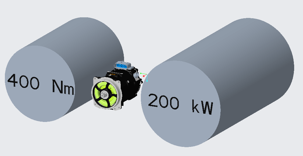
Figure 1. Relative size of air cooled industrial electric motors compared to the EVT motor. [1]
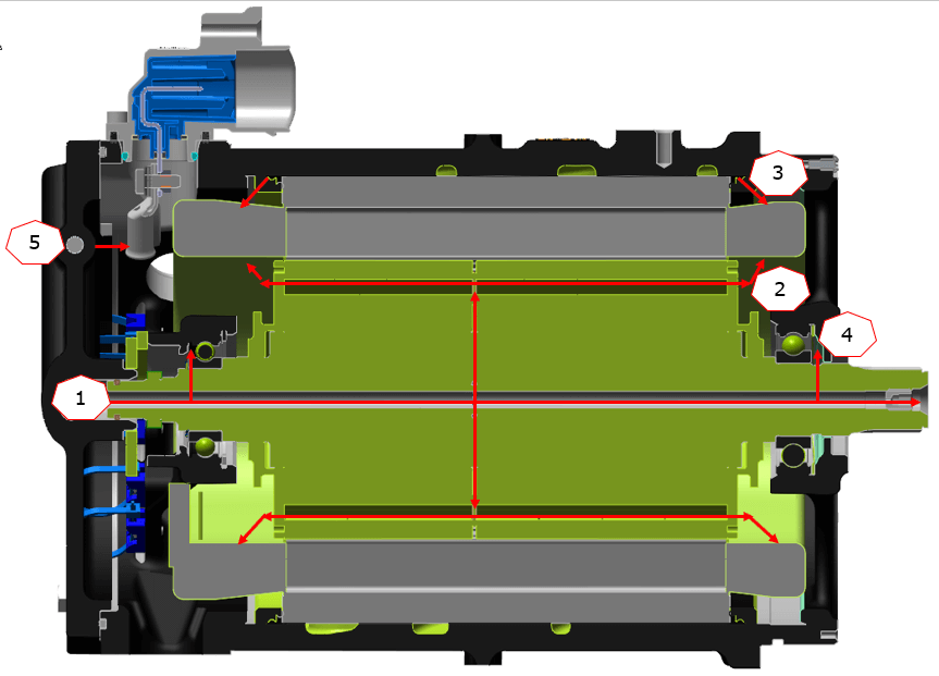
The electric motors are permanent magnet, synchronous, random wound, 4 pole-pair design. The motors have a nominal 214 mm OD rotor and are scalable by length to provide a broad power range. A permanent magnet design was chosen due to its high efficiency. High power density was achieved by directly cooling motor end-turns, stator, rotor magnets and bolted phase lead connections with oil. The resulting power density compared to some commonly available air-cooled industrial motors is shown in Figure 1 [1]. The oil supply to the motor is from the transmission through the motor mounting face, eliminating external hoses or lines and reducing leak points. Cooling oil is routed around the stator OD to the end coil spray rings and non-drive end cover. The non-drive end cover distributes oil to the rotor through an axial feed and radial exit holes in the rotor were designed to minimize centrifugal pumping effects and “flatten” the oil consumption vs rotor speed. A key advancement in cooling was developed which the originators informally called “Spin Spray” (US Patent #11,509,178 B2, represented in Figure 2) [2]. This advancement lowered cooling oil requirements by utilizing the same flow to cool the rotor magnets and the end-coils while keeping oil out of air gap to reduce viscous drag. Oil jets in the bottom of the spray ring were eliminated (bottom end coils were passively cooled by oil from top jets) further reducing oil consumption without compromising power density. Reducing oil consumption was key to minimize impact on the transmission lubrication system, improve efficiency and reduce cost.

Figure 2. Cross section of motor showing cooling and lubrication paths. 1: Rotor oil inlet, 2: Oil exiting rotor and cooling end coils, 3: Oil cooling from spray rings, 4: Rotor bearing lubrication, 5: Connector cooling.
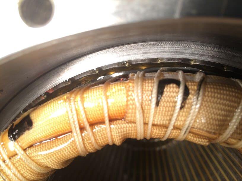
Maintaining oil jet velocity under all conditions is also important for cooling to be effective. At low velocities the oil would adhere to the spray ring and not touch the end-coils, which would result in overheating and low winding life as shown in Figure 3 [3].

Figure 3. Example of poor oil jet formed due to low jet velocity. Oil is adhering to the spray ring and not contacting the end-coils. [3]
The Inverter is a solid state, variable frequency drive, cooled by a low temperature water-ethylene glycol circuit (WEG). The inverter uses Insulated Gate Bipolar Transistor semiconductors (IGBT’s) and is designed and manufactured by John Deere. The inverter design is a “dual” inverter concept; where two inverter power stages are packaged into the same housing to improve power density and decrease cost. The electrical components are fully sealed inside a housing to protect them from dust and moisture. Extensive environmental and vibration testing was performed to make sure the electronics are “ruggedized” for offroad applications. The inverter hardware, software and controls were developed internally by John Deere allowing for the implementation of several advanced control and protection schemes that were key in successfully integrating the electric drive system with the tractor. The inverter utilizes a WEG liquid cooled cold plate provided through a dedicated low temperature cooling circuit. Key components in the inverter including the IGBTs and high current bus bars are thermally bonded to the cold plate delivering rated power with coolant temperatures up to 75 °C and achieving the required power density for successful vehicle integration. The temperature delta to ambient of the low temperature radiator is relatively low and maintaining target coolant temperatures in all corner case conditions is challenging. The inverter hardware was designed with overload capability and inverter software control features were implemented to allow the inverter to reliably operate across a wide range of coolant temperature, flow rate, and drivetrain load conditions.
The design and implementation of an electric drive system for off-road applications present unique challenges that require innovative solutions. Through a comprehensive approach to thermal protection and component durability, we have established a foundation for the successful deployment of electric drive systems in demanding off-road environments.
References
[1] “Grainger Industrial Supply,” [Online]. Available: www.grainger.com. [Accessed 26 February 2024].
[2] M. L. Kuhl, C. P. Neumann and R. K. Salamon, “Electric Machine Distributed Cooling System and Method”. United States of America Patent 11,509,178 B2, 22 November 2022.
[3] John Deere Coffeyville Works R&D, “Stator Lube Jet Performance,” JDCW, Coffeyville, 2018.

Mr. Roger Burjes, Deere & Company, Cedar Falls, Iowa

Mr. Jake Pence, Deere & Company, Moline, Illinois

Mr. Clayton Janasek, Deere & Company, Moline, Illinois